Disclaimers
Important Notice
Copyright © MENRED ESS Inc. All rights reserved.
No part of this document may be reproduced, stored in a retrieval system, or transmitted by any means—electronic, mechanical, photographic, magnetic, or otherwise—without the prior written permission of MENRED ESS In.
The content in this document is believed to be accurate and reliable at the time of publication. However, MENRED ESS assumes no responsibility for any issues arising from the use of this material. MENRED ESS reserves the right to make changes to the content, specifications, or design of the product or document without prior notice. For the latest updates, please visit the MENRED ESS website at https://menred-ess.com.
While every effort is made to ensure accuracy, discrepancies may occur. MENRED ESS does not guarantee the completeness or correctness of the information, and the user is responsible for verifying the suitability of the product for their specific application.
This manual provides detailed instructions for the proper installation of the MENRED ESS LFP.6144.W Series Lifepo4 Battery 51.2V. It is important to thoroughly read and follow the instructions to ensure safe and efficient installation. Failure to adhere to these guidelines could result in system malfunction, safety hazards.
The information and instructions contained in this manual are accurate as of the publication date. However, product specifications and configurations may change without notice. The illustrations are for reference purposes only, and the actual components may differ.
By proceeding with the installation, you acknowledge that MENRED ESS is not liable for any damages resulting from improper installation or failure to follow safety procedures.
Choose and set up the installation location
Follow these requirements when choosing an installation site
General guidelines and requirements
![]() The battery must be secured to a wall using the supplied mounting bracket and the installation location must be adjacent to a wall.
The battery must be secured to a wall using the supplied mounting bracket and the installation location must be adjacent to a wall.![]() When installed indoors, the battery must not be obstructed by any building structure, room furniture or equipment.
When installed indoors, the battery must not be obstructed by any building structure, room furniture or equipment.![]() The battery shall not be exposed to direct sun or rain.
The battery shall not be exposed to direct sun or rain.![]() Because the battery has a natural convection, the installation site mustbe clean, dry and well ventilated.
Because the battery has a natural convection, the installation site mustbe clean, dry and well ventilated.![]() The installation location must allow easy access to the battery forinstallation and maintenance.
The installation location must allow easy access to the battery forinstallation and maintenance.![]() The battery shall not be exposed to direct sun or rain.
The battery shall not be exposed to direct sun or rain.
Restricted locations
![]() Residential rooms
Residential rooms![]() Wall or ceiling niches
Wall or ceiling niches![]() Entrance/exit areas or below a staircase/passage
Entrance/exit areas or below a staircase/passage![]() Environments with humidity and condensed water level of over 90%
Environments with humidity and condensed water level of over 90%![]() Earthquake zones where additional safety measures are required
Earthquake zones where additional safety measures are required![]() Sites at altitudes of more than 2000 meters above the sea level
Sites at altitudes of more than 2000 meters above the sea level![]() The battery shall not be exposed to direct sun or rain.Sites exposed to direct sunlight or sites where the ambient temperature may exceed the specified maximum temperatures
The battery shall not be exposed to direct sun or rain.Sites exposed to direct sunlight or sites where the ambient temperature may exceed the specified maximum temperatures![]() Near flammable materials or gases or explosive environments
Near flammable materials or gases or explosive environments
Clearance
Observe the following minimum clearance:
![]() 20 cm from all sides of the battery module
20 cm from all sides of the battery module![]() 30 cm from another battery moudle or any heat source, such as water heater unit, gas-fueled heater, air contitioning unit or any other equipment
30 cm from another battery moudle or any heat source, such as water heater unit, gas-fueled heater, air contitioning unit or any other equipment![]() 100 cm from emergency exits
100 cm from emergency exits![]() 30 cm from doors
30 cm from doors![]() 25 cm from windows
25 cm from windows![]() 20 cm from air vents
20 cm from air vents![]() 20 cm from other devices
20 cm from other devices

Dimensions
Note the following dimensions:| Width | Height | Depth | |
|---|---|---|---|
| Battery Module | 600mm | 440mm | 210mm |
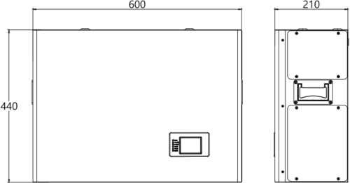
Battery Dimensions
Residential barrier
To prevent the spread of fire, install a non-combustible barrier on the opposite side of the wall or structural surface where the battery is mounted.
If the installation surface is not made of non-combustible material, a non-combustible barrier should be placed between the battery and the wall or structural surface.
If the battery pack is mounted on a wall or within 300mm from a wall that separates the energy storage system from a residential space, ensure that the distance from other structures or objects is increased.
Install the battery

Configurations
The system features a modular and scalable design, allowing additional battery modules to be added as needed. Up to 16 battery modules can be paralleled, expanding the total system capacity to 98.24kWh.
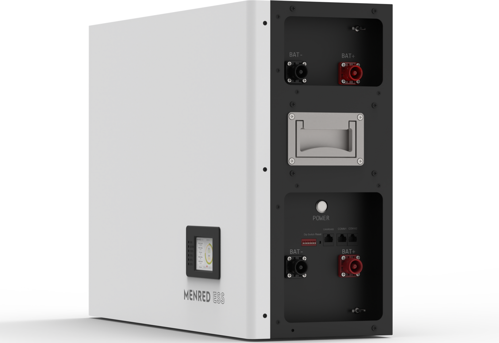
LFP.6144.W
Single Battery Module Description
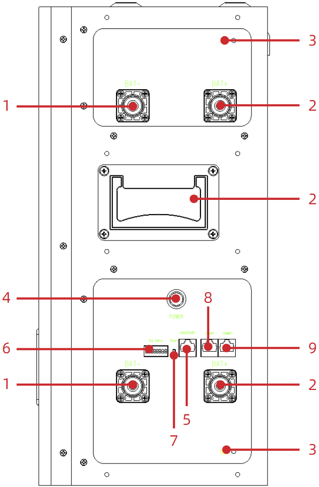
Battery Module
| 1 | DC Bat – Connector | 6 | Dip Switch |
|---|---|---|---|
| 2 | DC Bat + Connector | 7 | Reset Button |
| 3 | Grounding Terminal | 8 | COMM1 Communication Socket |
| 4 | Power Button | 9 | COMM2 Communication Socket |
| 5 | CAN / RS485 Communication Socket |
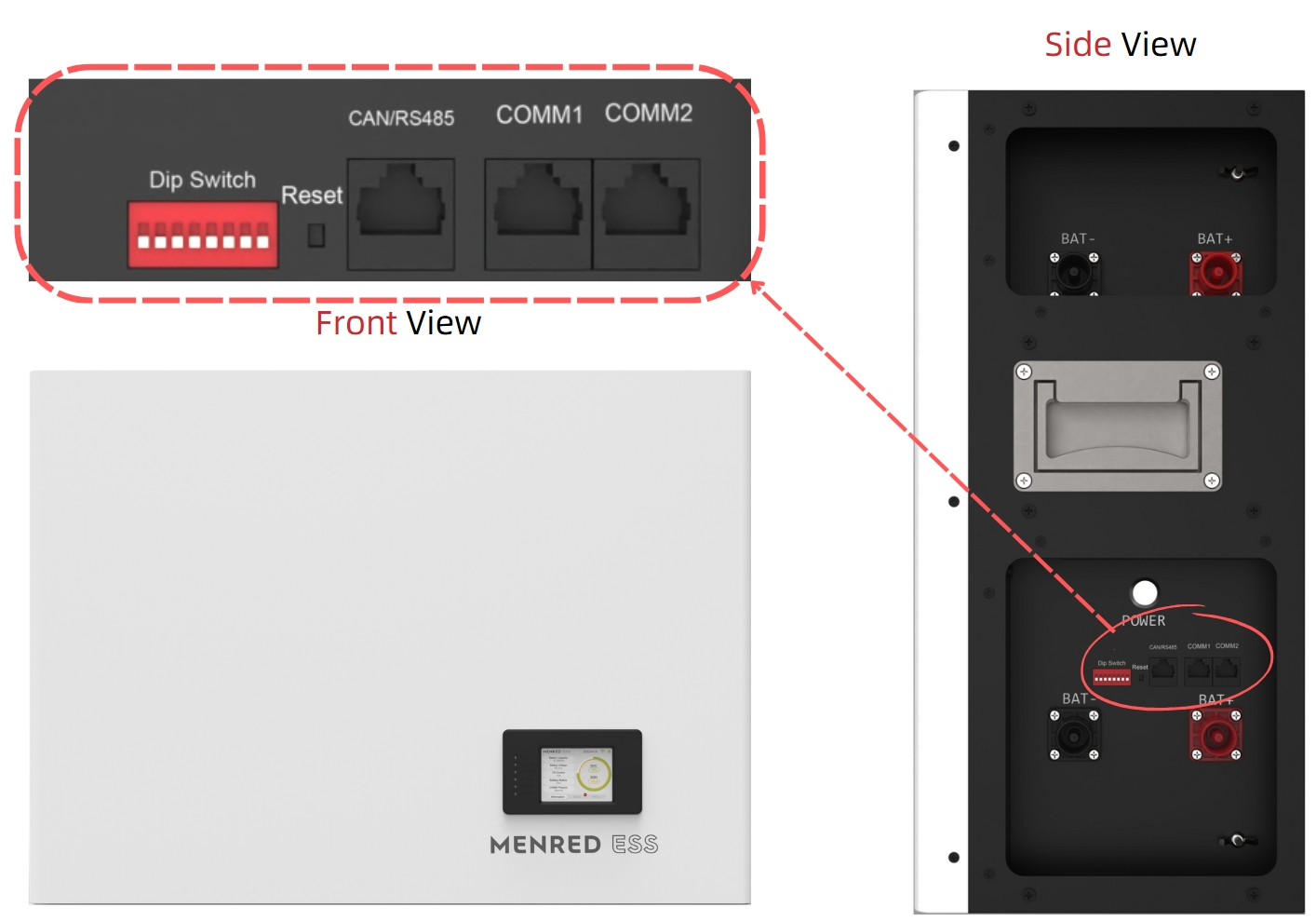
Battery Module(LFP.6144.W) – Physical Overview
Parallel Capacity and Charge/Discharge Power
The images below illustrate a connection method that scales both energy storage capacity and charge/discharge power
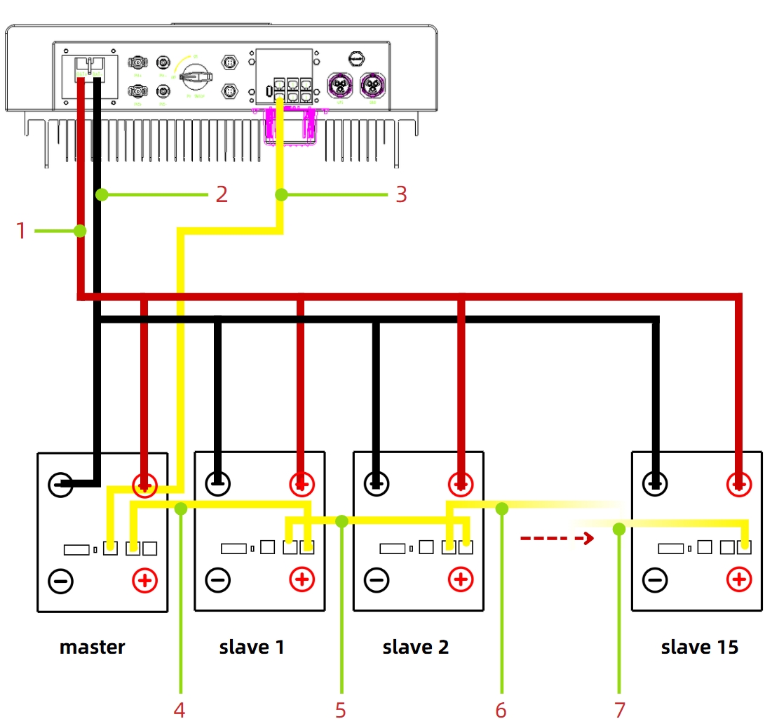
| 1 | DC Bat+ Cable (Battery – Inverter) |
| 2 | DC Bat- Cable (Battery – Inverter) |
| 3 | Communication Cable (Master Battery CAN / RS485 Communication Socket – Inverter) |
| 4 | Communication Cable (Master Battery COMM1 Communication Socket – #1 Slave Battery COMM2 Communication Socket) |
| 5 | Communication Cable (#1 Slave Battery COMM1 Communication Socket – #2 Slave Battery COMM2 Communication Socket) |
| 6 | Communication Cable (#2 Slave Battery COMM1 Communication Socket – #3 Slave Battery COMM2 Communication Socket) |
| 7 | Communication Cable (#14 Slave Battery COMM1 Communication Socket – #15 Slave Battery COMM2 Communication Socket) |
Parallel Capacity, not Parallel Charge/Discharge Power
The images below illustrate a connection method that increases total energy storage capacity while keeping the system’s charge/discharge power unchanged .
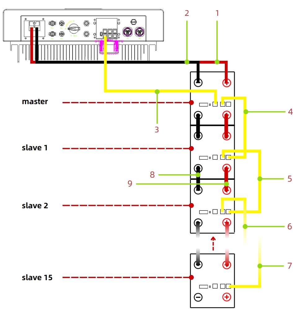
| 1 | DC Bat+ Cable (Master Battery – Inverter) |
| 2 | DC Bat- Cable (Master Battery – Inverter) |
| 3 | Communication Cable (Master Battery CAN / RS485 Communication Socket – Inverter) |
| 4 | Communication Cable (Master Battery COMM1 Communication Socket – #1 Slave Battery COMM2 Communication Socket) |
| 5 | Communication Cable (#1 Slave Battery COMM1 Communication Socket – #2 Slave Battery COMM2 Communication Socket) |
| 6 | Communication Cable (#2 Slave Battery COMM1 Communication Socket – #3 Slave Battery COMM2 Communication Socket) |
| 7 | Communication Cable (#14 Slave Battery COMM1 Communication Socket – #15 Slave Battery COMM2 Communication Socket) |
| 8 | DC Bat- Cable (Battery – Battery ) |
| 9 | DC Bat+ Cable (Battery – Battery ) |
Parallel CAN Communication Dial Settings
Refer to the CAN communication dialing summary table to select the appropriate dial settings.
LFP.6144.W CAN Communication DIP Switch Configuration
This PDF contains a detailed summary of DIP switch settings for parallel communication. Click the button below to download.
[Download Configuration Guide]

